THEORY OF OPERATION
SERIES A-100
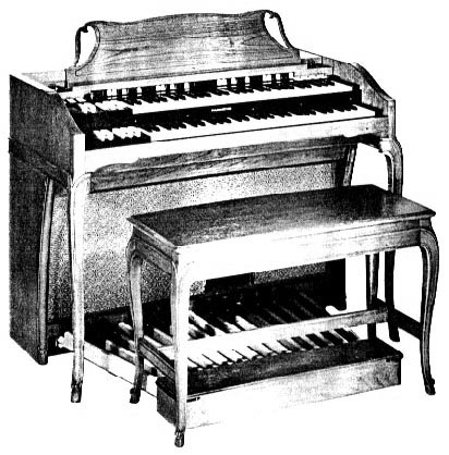
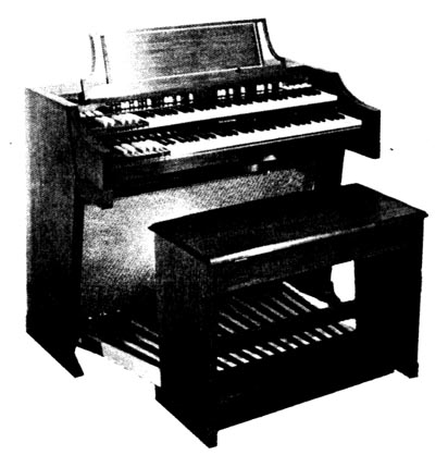
Figure 1
These Models of The Hammond Organ contain the entire tone-producing mechanism, which is completely electrical in operation. Within it are produced all the tones and tone combinations of the organ. The electrical waves are made audible by suitable amplifiers and loud speakers, contained within the console. The block diagram (Figure 7) shows the chief components of the instrument.
Electrical impulses of various frequencies are produced within a unit known as the "tone generator", containing a number of "phonic wheels" or "tone wheels" driven at predetermined speeds by a synchronous motor and gear arrangement. Each phonic wheel is similar to a gear, with high and low spots, or teeth, on its edge. As the wheel rotates these teeth pass near a permanent magnet, and the resulting variations in the magnetic field induce a voltage in a coil wound on the magnet. This small voltage, when suitably filtered, produces one note of the musical scale, its pitch or frequency depending on the number of teeth passing the magnet each second.
A note of the organ, played on either manual or the pedal keyboard, generally consists of a fundamental pitch and a number of harmonics, or multiples of the fundamental frequency. The fundamental and eight harmonics available on each playing key are individually controllable by means of drawbars and preset keys. By suitable adjustment of these controls the player is enabled to vary the tone colors at will.
The resulting signal passes through the expression or volume control and through the preamplifier (where vibrato is introduced) to the power amplifier and the self-contained speakers.
Reverberation is added electrically by a second amplifier which drives a reverberation speaker, also located in the console.
DESCRIPTION
Each Hammond Organ console (Fig. 1) includes two manuals or keyboards: the lower, or Great, and the upper, or Swell; and a pedal keyboard of 25 keys. The operation of the controls of this model is covered in the following paragraphs.
STARTING THE ORGAN |
|
 |
To start the organ, hold the "start" switch (Fig. 2) in "on" position for approximately eight seconds. Still holding it, push the "run" switch on "on" position. After leaving both switches on for about four seconds, release the start switch to return to its normal position. If the console is very cold, or if a frequency regulater is used, it may be necessary to hold the start switch slightly longer. A pilot light shows when the organ is turned on. |
| PRESET KEYS | |
|
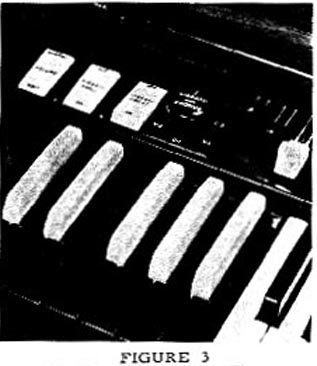
At the left end of each manual are twelve keys identical to the playing keys except reversed in color (Fig.3). When a preset key is depressed it locks down and is released only when another is depressed. The exception to this is the cancel key at the extreme left, which serves only to release any key which may be locked down. Only one preset key is used at one time. If by mistake two are depressed and locked, they may be released by means of the cancel key. Each preset key, with the exception of the cancel key and the two "adjust" keys at the extreme right of the group, makes available a different tone color which has been set up on the preset panel located inside the console. These tone colors are set up at the factory in accordance with a standard design which :as been found to best meet the average organist's reqirements. They may be changed, if desired, by removing the back of the console and changing the preset panel connections in accordance with instructions on a card located near the preset panel. When either "adjust" key is depressed, the organ speaks with whatever tone color is set up on the harmonic drawbars associated with that key. The percussion effect can be used only, when the upper manual 'B' preset key is depressed (see "percussion" also). |
HARMONIC DRAWBARS |
|
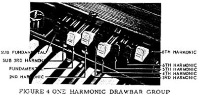 |
Each console has four sets of harmonic drawbars, two for each manual. Figure 4 shows one group of harmonic drawbars, by which the organist is enabled to mix the fundamental and any, or all, of eight different harmonics in various proportions. The third bar from the left controls the fundamental, and each of the other bars is associated with a separate harmonic. If a drawbar is set all the way in, the harmonic it represents is not present in the mixture. Each drawbar may be set in eight different positions by the organist in addition to the silent position. Each position, as marked on the drawbars, represents a different degree of intensity of the harmonic it controls. When drawn out to position 1, the harmonic it represents will be present with minimum intensity; when drawn out to position 2, with greater intensity; and so on up to position 8. A tone color is logged by noting the numerical position of the various drawbars, For instance, the tone set up on Figure 4 is known as tone 34 630 5210. After a tone is so logged it may be made available again by setting the harmonic drawbars to that number. |
HARMONIC DRAWBARS FOR THE PEDALS
In the pedals the harmonic resources have been combined into two drawbars which may be used separately or in combination. When the left drawbar is used, emphasis is given to the lower harmonics, and similarly the higher harmonics are emphasized when the right drawbar is used. The pedal drawbars are located between the two sets of manual drawbars.
NORMAL - SOFT VOLUME CONTROL
This control (Fig. 3) is a tilting tablet which supplements the action of the expression pedal. In "soft" position it reduces the volume of the whole instrument. It is particularly useful when playing in a small room or when the organist wishes to practice without disturbing others.
EXPRESSION OR SWELL PEDAL
The swell pedal, located in the customary position, is operated by the right foot, and with it the volume of the organ may be controlled over a wide range. It operates on the two manuals and pedals equally; that is to say, once the manuals and pedals are balanced, they retain their relative balance over the entire swell pedal range.
VIBRATO |
|
|
The vibrato effect is created by a periodic raising and
lowering of pitch, and thus is fundamentally different from a tremolo, or loudness
variation. It is comparable to the effect produced when a violinist moves his finger back
and forth on a string while playing, varying the frequency while maintaining constant
volume. The vibrato mechanism includes an electrical time delay line, which shifts the phase of all tones fed into it. A rotating scanner, mounted on the main tone generator, picks up successive signals from various line sections. These signals represent various amounts of phase shift, and the combination of signals produces a continuous frequency variation. These Models have the "selective vibrato" feature which makes the vibrato effect available on either manual separately or on both together. Two tilting tablets control the vibrato for the two manuals, while the rotary switch (Figure 5) selects the degree of vibrato or vibrato chorus effect. The "Great" tablet controls the vibrato for the pedals as well as for the Great manual. |
PERCUSSION |
|
|
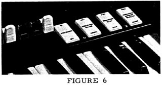
The "Touch-Response Percussion" feature is controlled by four tilting tablets (Fig. 6) at the upper right side of the manuals. Percussion is available only on the upper manual and only when the 'B' preset key is depressed. The four tablets (from left to right) select Percussion on or off, normal or soft Volume, fast or slow Decay, and second or third Harmonic tone quality. Percussion tones are produced by borrowing the second or third harmonic signal from the corresponding manual drawbar, amplifying it, returning part of the signal to the same drawbar, and conducting the balance of the signal through push-pull control tubes where its decay characteristics are controlled. The Percussion signal is then combined with the signal from the manuals and pedals after the vibrato circuit but ahead of the expression control. The control tubes are keyed by the eighth harmonic key contacts and busbar. |
TONE GENERATOR
The main tone generator furnishes 91 different musical frequencies. It includes a tone wheel, magnet, and coil for each frequency. Mounted on top of the generator are tuned filters to insure purity of the tones.
PREAMPLIFIER
The Preamplifier is located within the console, suspended from the main generator shelf. Its purpose is to amplify the signals before sending them to the amplifier. This unit also houses the electrical portion of the swell or expression control .
POWER AMPLIFIER
A twelve watt amplifier is mounted on the lower shelf of the console. It receives the signal from the Preamplifier and increases it in power to drive the two 12" speakers.
REVERBERATION SYSTEM
To the left of the amplifier are the reverberation amplifier and reverberation unit. A portion of the output signal of the power amplifier passes through the reverberation unit to the reverberation amplifier and this drives a third 12" speaker housed within the console. The degree of reverberation heard can be regulated by rotating the knob marked "Reverberation Control" shown in Figure 5.
In operation, an electrical signal from the amplifier is applied to the driver unit in the reverberation device which then converts the electrical signal into mechanical energy. This energy is transmitted through springs to a pickup unit where a part of it is converted back to electrical energy. The remaining portion is reflected back to the driver and again back to the pickup at a time interval determined by the spring lengths. This transaction continues until the signal energy is reduced to one millionth of its original value. The transfer time from driver to pickup and the reflections within the system itself produce the reverberation effect.
USE OF TONE CABINETS
Any Hammond Tone Cabinet may be attached to these organs by use of the proper cable plugged into the outlet to the right of the AC input plug. Reverberation from the console is not transferable to these Tone Cabinets. further information on connection of multiple tone cabinet installation, refer to Section 4 of Service Manual covering larger models.
ECHO CONTROL
If a tone cabinet as mentioned above, is added, an echo control can also be attached. This permits use of the self contained speaker or the added tone cabinet independently. One position of the control permits both to play simultaneously. Complete instructions for its installation accompanies the kit.
INSTALLATION AND MAINTENANCE
The organ must be connected to a regulated-frequency source of the voltage and frequency specified on the name plate. If the frequency is not regulated, the pitch of the organ will be irregular.
When a console is set up for operation, the anchoring must be loosened so that the generator will float freely on its spring suspension system. No damage will result if this is not done, but the console will sound noisy, and the same is true if the anchoring is loosened but the console is not level. If the console is to be moved a long distance the anchoring should be tightened during such moves.
Instructions for loosening and tightening the generator in the console are given on the instruction card contained in the bench.
The tone generator is lubricated by putting oil into cups inside the console. Add oil in accordance with the instruction within the console.
When placement of console has been completed after loosening of generator, as described above, the reverberation unit if necklace type should be unlocked by moving its lever "up". The unit should be again locked whenever the console is moved, even if only a few feet. Consoles, serial number above 6127 do not require any locking or unlocking operation.
To replace the pilot lamp, remove the back cover, if the console has one. It is a pin type lamp, 6.3 volts, #12.

TECHNICAL SECTION
THE HAMMOND TONE GENERATOR
The A-100, A-101 and A-102 embodies the Hammond electro-mechanical tone generator as its source of tone. A picture of this generator is shown below.
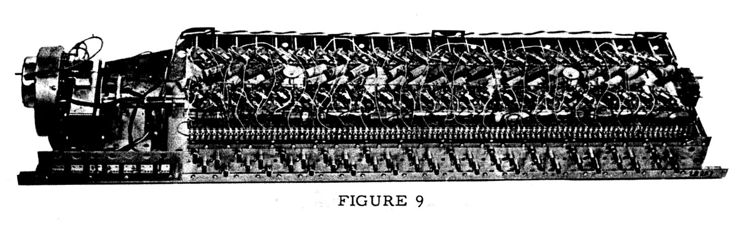
The generator assembly includes a shaded-pole induction motor for starting, a non-self-starting synchronous motor for driving the unit after it is started, and a Vibrato Scanner mounted on the synchronous motor. The entire assembly is mounted on two long steel angles which also provide the means of mounting the tone generator in the console. The method of mounting is such as to minimize the transmission of vibration from the tone generator to the console.
A drive shaft, resiliently coupled to the synchronous running motor, extends the entire length of the generator. Twenty-four driving gears, two each of twelve sizes, are mounted on this shaft, and the drive shaft itself is divided into several sections connected by flexible couplings. The starting motor is mounted at the end of this drive shaft, opposite to the synchronous motor.
STARTING AND SYNCHRONOUS MOTORS
As mentioned above, a shaded-pole induction motor is used for starting the generator and is located at the right end of the generator as viewed from the back. The rotor of this motor will slide endwise when current is supplied and engage a pinion on its shaft with a gear on the generator driving shaft.
When the organ is started, the starting switch is turned on and held for about 8 seconds while the starting motor brings the system up to slightly greater than synchronous speed. The "run"switch is then turned on. This switch simultaneously connects the synchronous motor and introduces a resistor in series with the starting motor thus reducing its driving power. With a braking action of the synchronous motor and a loss of power of the starting motor, the system slows to synchronous speed and the synchronous motor begins to carry the load. A period of about 4 seconds should be allowed for this to take place, after which the starting switch may be released. The starting switch springs back to the "off" position, and turns off the starting motor, which is then disengaged from the rotating shaft by a spring.
It should be noted that the synchronous motor can supply power only at synchronous speed. Therefore, if for any reason the system fails to reach synchronous speed it will not continue to run after the starting switch is released. Failure to start properly is usually due to increased oil viscosity or low line voltage and may sometimes be overcome by a increase in starting time.
As the schematic diagram indicates, the "run" switch in its "off" position shorts out the wirewound resistor attached to the line panel. If the "run" switch is defective in its "off" position, the generator will not start because this resistor will be permanently in series with the starting motor. Before assuming that there is anything amiss with the motors, short out this resistor and start the generator in the normal manner. If the generator operates satisfactorily, replace the "run" switch.
THE TONE WHEELS
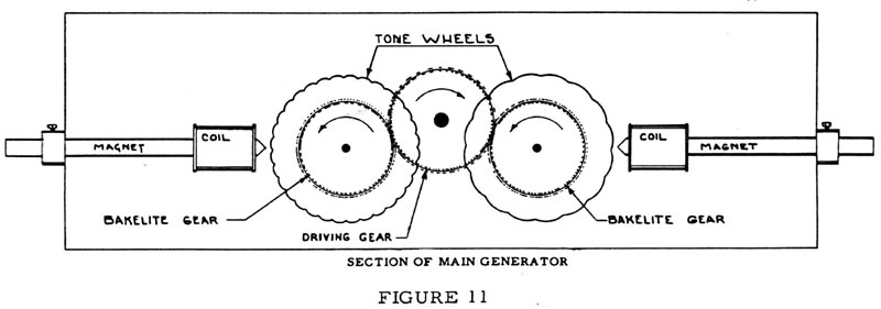
The main generator is a long structure in which are mounted 48 rotating assemblies, each consisting of a shaft and two discs known as tone or phonic wheels. These assemblies are coupled resiliently to the drive shaft. Each of the driving gears engages two bakelite gears associated with rotating assemblies on opposite sides (See Figure 11). These bakelite gears rotate freely on the shafts with the tone wheels, and are coupled to their respective assemblies by a pair of coil springs. There are 12 sizes of bakelite gears, corresponding to the 12 sizes of driving gears. Thus 4 of the tone wheel assemlies, each with 2 tone wheels, run at each of 12 speeds.
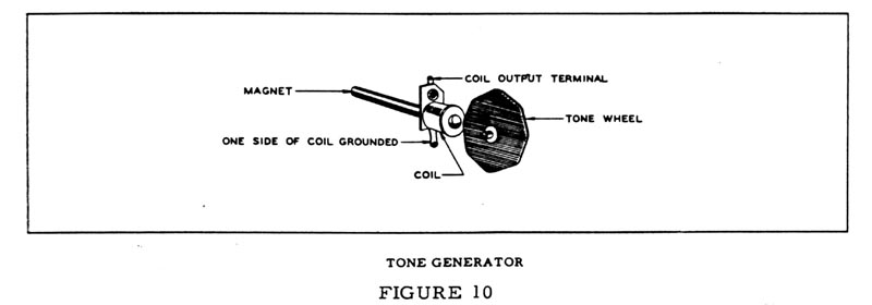
Each tone wheel is a steel disc about 2 inches in diameter, accurately machined with a definite number of high and low points on its edge (See Figure 10). Each high point on a tone wheel is called a tooth. The number of teeth on each of these tone or phonic wheels, in conjunction with the speed at which the tone wheel is revolving, determines the frequency of the tone generated.
Each driving gear, with its two bakelite gears and four tone wheels, runs in a separate compartment magnetically shielded from the rest by steel plates which divide the generator into a series of bins.
All four tone wheels in any one compartment run at the same speed. The individual tone wheel shafts are mounted in bearings made of a special porous bronze and each of these bearings is connected to the oiling system by a cotton thread from the oil trough. Thus, oil from the trough is carried by capillary action to all bearings, penetrating them and lubricating the actual bearing surface. The drive shaft and both motors are lubricated in a similar manner. It is very important to use the recommended grade of oil, as it is essential to the proper operation of the organ that the generator be well lubricated. If oil of other grades is used, it is likely the the generator may be sluggish in starting, and in time the threads may gum up and prevent the proper flow of oil. Follow oiling instructions within the console.
The two spring couplings on the motor shaft, the flexible couplings between sections of the drive shaft, and the tone wheel spring couplings all contribute to absorbing variations in motor speed. The synchronous motor does not deliver absolutely steady power, but rather operates with a series of pulsations, one with each half cycle. If the tone wheels were rigidly coupled to the motor, this slight irregularity would carry extra frequencies into each tone wheel. In addition, "hunting" is suppressed by the resilient couplings and inertia members of the synchronous motor proper.
Associated with each tone wheel is a magnetized rod about 1/4 of an inch in diameter and 4 inches in length, with a coil of wire wound near one end (See Figure 10). The tip of the magnet at the coil end is ground to a sharp edge and mounted near the edge of the tone wheel. Each time a tooth passes this rod it causes a change in the magnetic field, which induces a small voltage in the coil, the frequency being determined by the number of teeth and the wheel speed.
Small coils are used on the higher frequency magnets and larger coils on the lower frequencies. It is found that large pole pieces are needed on the low frequency magnets to give proper output, but it is necessary to use smaller ones on the high frequencies to prevent excessive iron losses.
Some of the coils have copper rings mounted on them for the purpose of reducing harmonics. As these are used only on fairly low frequency coils, the eddy current loss in such a ring is small for the fundamental frequency of that coil, but high for its harmonics. This has the effect of reducing the relative intensities of any harmonics which may be produced by irregularites in the tone wheels. The wheels are cut so to give as nearly a sine wave as possible, but the generated voltage seldom reaches that ideal condition, since even a slight change in the air gap will change the wave form. The tip of each magnet, as well as the edge of each tone wheel, is coated with lacquer to prevent corrosion, for, should oxidation set in, the change in tooth shape would introduce irregular frequencies.
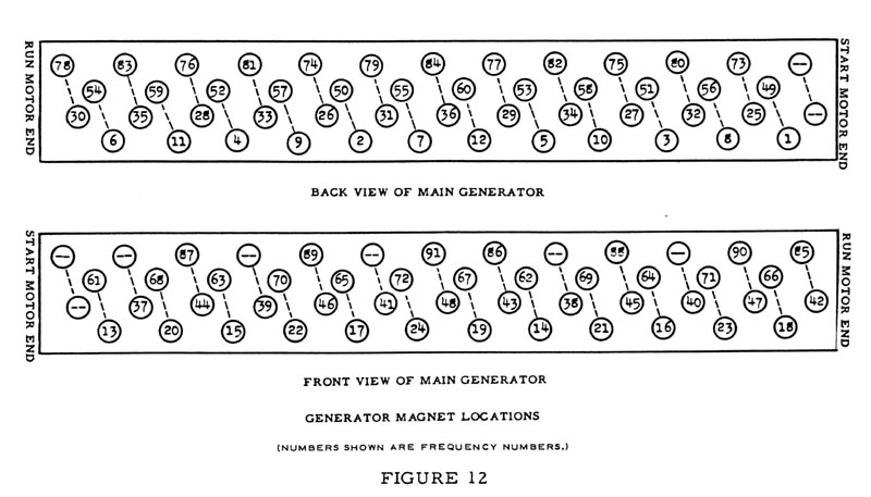
Locations of the various magnet and coil assemblies are shown in Figure 12. They are identified by their frequency numbers, and the broken line between any two numbers indicates that these two frequencies are supplied by one tone wheel assembly.
Each magnet gap is set at the factory with the set screw partially loosened, while observing an output meter. Experience has shown that the magnets seldom need adjustment and that setting them without proper equipment involves danger of damaging both magnet and wheel. Therefore it is not recommended that the service man attempt this adjustment.
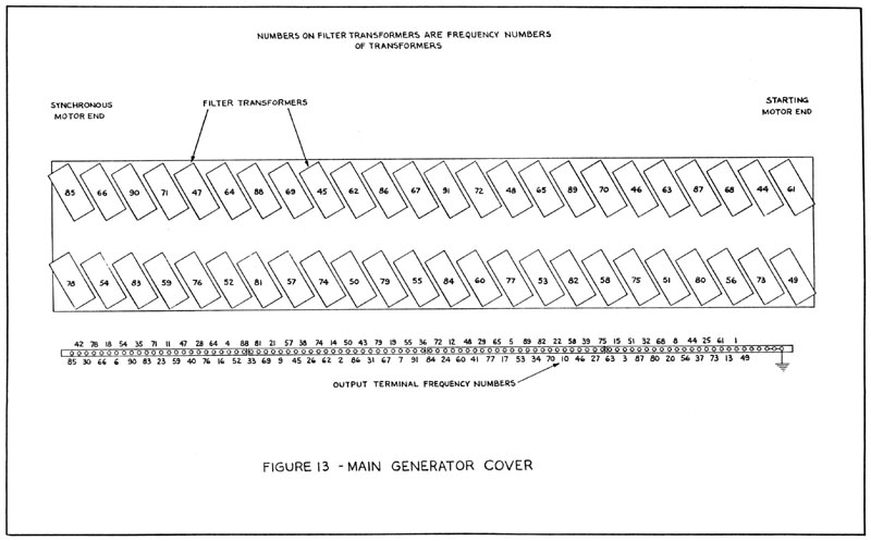
GENERATOR FILTERS
As a means of eliminating any vagrant harmonics that may be present, there are filters consisting of small transformers and condensers associated with certain frequencies. The transformers have a single tapped winding, and this tap is grounded, so one side, which is connected to the corresponding magnet coil through a condenser, forms a resonant circuit for the fundamental frequency of that coil. This tends to emphasize the fundamental and suppress harmonics.
Locations of these transformers are shown in Figure 13. They are also shown in the schematic.
These transformers and condensers are mounted on the top of the generator assembly. The transformers are mounted at an angle, thus minimizing interference between them. The cores of the transformers are made of a special iron, and the number of laminations used is adjusted to secure the proper inductance.Wires from the magnet coils connect to the transformers, and wires from the transformers lead to the terminal strip on the generator.
This terminal strip carries the output frequencies of the generator, which are arbitrarily numbered from 1 to 91 in order of increasing frequency. This frequency numbering is continued throughout the instrument. The frequencies are not in order on the terminal strip, and Figure 13 indicates the arrangement. Several terminals at the right end are grounded to the generator frame and serve to ground the manuals and pedals.
Transformers and condensers are not used below frequency 44, but a length of resistance wire shunts each generator. Frequencies 44 to 48 have transformers only, while both transformers and condensers are used for frequencies 49 to 91.
Two condenser values are used - 0.255 mfd for frequencies 49 to 54, and 0.105 mfd for frequencies 55 to 91. The transformers are all different. Each transformer is matched to its condenser and any replacements are supplied as matched pairs by the factory.
THE MANUAL CHASSIS ASSEMBLY |
|
 |
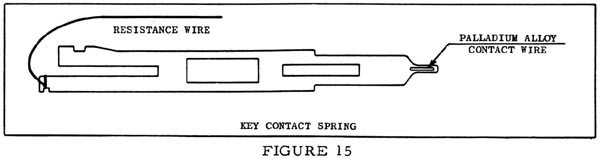
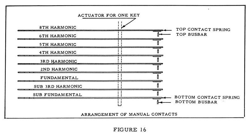
The manual chassis assembly, Fig. 14, includes the upper and lower manuals and the preset panel. It has a terminal strip under each manual to accommodate the necessary frequency wires from the tone generator assembly. Each manual has 61 playing keys, 9 preset keys, and 2 adjust keys, each of which operates nine small bronze contact springs with precious metal points (See Figure 15). When a key is pressed these points make contact with nine busbars extending the entire length of the manual. The busbars also have precious metal contact surfaces. The nine contact springs under each key carry the nine harmonics of the particular note with which they are associated (See Figure 16) and are connected by resistance wires to the proper terminals on the terminal strip. Therefore all key contacts are alive whenever the generator is running. |
 |
|
ARRANGEMENT OF MANUAL CONTACTS
When a playing key is pressed, its nine frequencies are impressed on the nine busbars of the manual. As there are no wires connected to these busbars, a preset or adjust key must be depressed before any circuit can be completed. Each preset and adjust key has nine contacts exactly like those of the playing keys. These keys have a locking and trip mechanism which locks down one key at a time.The key at the extreme left end of the manual is a cancel key, with no contacts, which releases any preset or adjust key that happens to be depressed.
The adjust keys, A# and B, are connected by flexible wires, color-coded for easy identification, to the corresponding nine drawbars. The drawbars slide over nine busses which are connected to taps on the matching transformer. These correspond to different intensities of sound as shown by numbers on the drawbars.
The two left groups of drawbars are associated with the upper manual, while the two right groups work in conjunction with the lower manual. In each case the A# adjust key controls the left hand group of drawbars for that manual.
The nine preset keys, from C# to A inclusive, are wired to flexible leads terminating at the preset panel in the back of the console, where the various tone colors are set up by connecting each wire to a screw terminal corresponding to the desired intensity of the harmonic. These screw terminals are located on 9 horizontal bars, each representing a certain intensity for all wires attached to that bar.
The drawbar busses and the preset panel bars are connected in parallel to taps on the primary of the matching transformer.
Manual Busbar Shifters
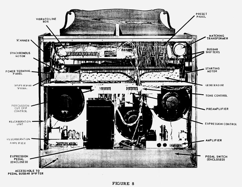
The precious metal contact surfaces of the key contacts and busbars are not subject to corrosion, and the manuals are sealed to exclude dust as far as possible. In spite of these precautions an occational particle of dust may lodge on a contact and cause the note to be scratchy, noisy, or silent, and for this reason a busbar shifting mechanism is provided on each manual to slide the busbars endwise and thus provide a fresh contact surface. The busbar shifter for each manual is a slotted stud near the right end of the manual as viewed from the back of the console (see rear view of console, Figure 8, for location) .
If any note becomes scratchy or silent, the key should first be struck 15 or 20 times in a rapid staccato manner to loosen the dirt. This will usually dislodge the particles and clear the note.
In case this procedure is not effective, the busbar shifter for that manual may be adjusted by turning the stud about two turns in either direction. It may sometimes be necessary to hold down the offending key while turning the busbar shifter, in order to wipe the contact clean.
Manual Wiring
Figure 19, a wiring chart for the playing manuals, will be helpful in tracing difficulties associated with the generator or manuals. Both manuals are wired alike.
Preset Panel
The tone signals from the preset keys are carried by color-coded wires to the divided preset panel in the back of the console.
Each preset wire, carrying a single harmonic, is fastened under a screw on the bar which represents the desired intensity of that harmonic. This is equivalent to setting a harmonic drawbar to the corresponding number. One part of the preset panel is used for the swell (upper) manual and the other for the great (lower) manual and pedals.
When shipped, each organ has its presets set up as shown in the playing instructions furnished with the organ. Preset combinations may be changed at will by removing the console back and following the directions on a card inside. This card is reproduced below. (Figure 17).

OPERATION OF MECHANISM ON PRESET KEYS
In their basic construction the preset keys are identical to the playing keys. Each has a plastic key mounted on a metal channel, pivoted in the rear and with a guide toward the front to minimize side motion.
On the front edge of each channel of the 9 preset keys and 2 adjust keys, two flat springs are attached, one 5/8" long of rather stiff material, and another approximately 3/4" long of softer material. The softer long spring is sandwiched on top of the stiff spring, nearest to the key. The cancel key has only one heavy spring approximately 1" long.
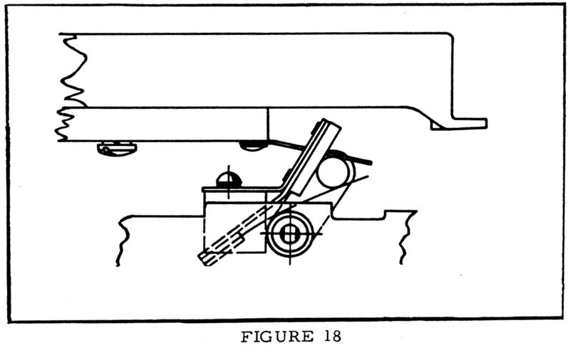
When a preset key is depressed, the longer soft spring is forced downward and snaps under a tubular rod which is part of the cradle. The cradle is constructed of two tubes approximately 6" long and assembled 3/4" apart. One tube is used as a fulcrum, the entire assembly being mounted perpendicular to the preset keys, A spring and bumper hold the cradle at a 60 degree angle toward the front of the console.
Once a key has been depressed, the soft spring remains under the tube. It is backed by the short stiff spring to give it sufficient tension to hold the key down. When the next preset key is depressed, the cradle is forced down and outward, permitting the previously operated key to come up, but again locking the one last depressed.
If two preset keys are depressed at once, both will lock down. The cancel key with its long stiff spring is then used and forces the cradle down, causing all preset keys depressed to return to their normal position. As there is no locking spring on the cancel key, it will immediately return to its normal position.
Replacement of Preset "Cradle" Return Spring
If it is determined that a new return spring is necessary on either manual, remove the console top and music rack and take the bolts holding the manual assembly out from the bottom of the console. Raise the upper manual, or both manuals, as necessary, to gain access to the screws holding the left hand end block of the manual needing the replacement. After removal of the end block, the end of the cradle assembly, as well as the broken return spring and its bracket, will be visible.
Remove the bracket and broken spring and discard. Replace, using Part No. AO-21709-0.
Install the new assembly so that the felt pad is above the preset cradle, and the flat spring is below the cradle, as shown in Figure 18. Clamp it in the center of the range of adjustment provided by the slot. Check all preset keys for operation, and adjust the position of the new assembly in case any keys do not operate correctly.
| Key Number | Note | Drawbar 1 | Drawbar 2 | Drawbar 3 | Drawbar 4 | Drawbar 5 | Drawbar 6 | Drawbar 7 | Drawbar 8 | Drawbar 9 |
| 1 | C | 13 | 20 | 13 | 25 | 32 | 37 | 41 | 44 | 49 |
| 2 | C# | 14 | 21 | 14 | 26 | 33 | 38 | 42 | 45 | 50 |
| 3 | D | 15 | 22 | 15 | 27 | 34 | 39 | 43 | 46 | 51 |
| 4 | D# | 16 | 23 | 16 | 28 | 35 | 40 | 44 | 47 | 52 |
| 5 | E | 17 | 24 | 17 | 29 | 36 | 41 | 45 | 48 | 53 |
| 6 | F | 18 | 25 | 18 | 30 | 37 | 42 | 46 | 49 | 54 |
| 7 | F# | 19 | 26 | 19 | 31 | 38 | 43 | 47 | 50 | 55 |
| 8 | G | 20 | 27 | 20 | 32 | 39 | 44 | 48 | 51 | 56 |
| 9 | G# | 21 | 28 | 21 | 33 | 40 | 45 | 49 | 52 | 57 |
| 10 | A | 22 | 29 | 22 | 34 | 41 | 46 | 50 | 53 | 58 |
| 11 | A# | 23 | 30 | 23 | 35 | 42 | 47 | 51 | 54 | 59 |
| 12 | B | 24 | 31 | 24 | 36 | 43 | 48 | 52 | 55 | 60 |
| 13 | C | 13 | 32 | 25 | 37 | 44 | 49 | 53 | 56 | 61 |
| 14 | C# | 14 | 33 | 26 | 38 | 45 | 50 | 54 | 57 | 62 |
| 15 | D | 15 | 34 | 27 | 39 | 46 | 51 | 55 | 58 | 63 |
| 16 | D# | 16 | 35 | 28 | 40 | 47 | 52 | 56 | 59 | 64 |
| 17 | E | 17 | 36 | 29 | 41 | 48 | 53 | 57 | 60 | 65 |
| 18 | F | 18 | 37 | 30 | 42 | 49 | 54 | 58 | 61 | 66 |
| 19 | F# | 19 | 38 | 31 | 43 | 50 | 55 | 59 | 62 | 67 |
| 20 | G | 20 | 39 | 32 | 44 | 51 | 56 | 60 | 63 | 68 |
| 21 | G# | 21 | 40 | 33 | 45 | 52 | 57 | 61 | 64 | 69 |
| 22 | A | 22 | 41 | 34 | 46 | 53 | 58 | 62 | 65 | 70 |
| 23 | A# | 23 | 42 | 35 | 47 | 54 | 59 | 63 | 66 | 71 |
| 24 | B | 24 | 43 | 36 | 48 | 55 | 60 | 64 | 67 | 72 |
| 25 | C | 25 | 44 | 37 | 49 | 56 | 61 | 65 | 68 | 73 |
| 26 | C# | 26 | 45 | 38 | 50 | 57 | 62 | 66 | 69 | 74 |
| 27 | D | 27 | 46 | 39 | 51 | 58 | 63 | 67 | 70 | 75 |
| 28 | D# | 28 | 47 | 40 | 52 | 59 | 64 | 68 | 71 | 76 |
| 29 | E | 29 | 48 | 41 | 53 | 60 | 65 | 69 | 72 | 77 |
| 30 | F | 30 | 49 | 42 | 54 | 61 | 66 | 70 | 73 | 78 |
| 31 | F# | 31 | 50 | 43 | 55 | 62 | 67 | 71 | 74 | 79 |
| 32 | G | 32 | 51 | 44 | 56 | 63 | 68 | 72 | 75 | 80 |
| 33 | G# | 33 | 52 | 45 | 57 | 64 | 69 | 73 | 76 | 81 |
| 34 | A | 34 | 53 | 46 | 58 | 65 | 70 | 74 | 77 | 82 |
| 35 | A# | 35 | 54 | 47 | 59 | 66 | 71 | 75 | 78 | 83 |
| 36 | B | 36 | 55 | 48 | 60 | 67 | 72 | 76 | 79 | 84 |
| 37 | C | 37 | 56 | 49 | 61 | 68 | 73 | 77 | 80 | 85 |
| 38 | C# | 38 | 57 | 50 | 62 | 69 | 74 | 78 | 81 | 86 |
| 39 | D | 39 | 58 | 51 | 63 | 70 | 75 | 79 | 82 | 87 |
| 40 | D# | 40 | 59 | 52 | 64 | 71 | 76 | 80 | 83 | 88 |
| 41 | E | 41 | 60 | 53 | 65 | 72 | 77 | 81 | 84 | 89 |
| 42 | F | 42 | 61 | 54 | 66 | 73 | 78 | 82 | 85 | 90 |
| 43 | F# | 43 | 62 | 55 | 67 | 74 | 79 | 83 | 86 | 91 |
| 44 | G | 44 | 63 | 56 | 68 | 75 | 80 | 84 | 87 | 80 |
| 45 | G# | 45 | 64 | 57 | 69 | 76 | 81 | 85 | 88 | 81 |
| 46 | A | 46 | 65 | 58 | 70 | 77 | 82 | 86 | 89 | 82 |
| 47 | A# | 47 | 66 | 59 | 71 | 78 | 83 | 87 | 90 | 83 |
| 48 | B | 48 | 67 | 60 | 72 | 79 | 84 | 88 | 91 | 84 |
| 49 | C | 49 | 68 | 61 | 73 | 80 | 85 | 89 | 80 | 85 |
| 50 | C# | 50 | 69 | 62 | 74 | 81 | 86 | 90 | 81 | 86 |
| 51 | D | 51 | 70 | 63 | 75 | 82 | 87 | 91 | 82 | 87 |
| 52 | D# | 52 | 71 | 64 | 76 | 83 | 88 | 80 | 83 | 88 |
| 53 | E | 53 | 72 | 65 | 77 | 84 | 89 | 81 | 84 | 89 |
| 54 | F | 54 | 73 | 66 | 78 | 85 | 90 | 82 | 85 | 90 |
| 55 | F# | 55 | 74 | 67 | 79 | 86 | 91 | 83 | 86 | 91 |
| 56 | G | 56 | 75 | 68 | 80 | 87 | 80 | 84 | 87 | 80 |
| 57 | G# | 57 | 76 | 69 | 81 | 88 | 81 | 85 | 88 | 81 |
| 58 | A | 58 | 77 | 70 | 82 | 89 | 82 | 86 | 89 | 82 |
| 59 | A# | 59 | 78 | 71 | 83 | 90 | 83 | 87 | 90 | 83 |
| 60 | B | 60 | 79 | 72 | 84 | 91 | 84 | 88 | 91 | 84 |
| 61 | C | 61 | 80 | 73 | 85 | 80 | 85 | 89 | 80 | 85 |
| Frequency Number | ||||||||||
Figure 19
PEDAL SWITCH ASSEMBLY
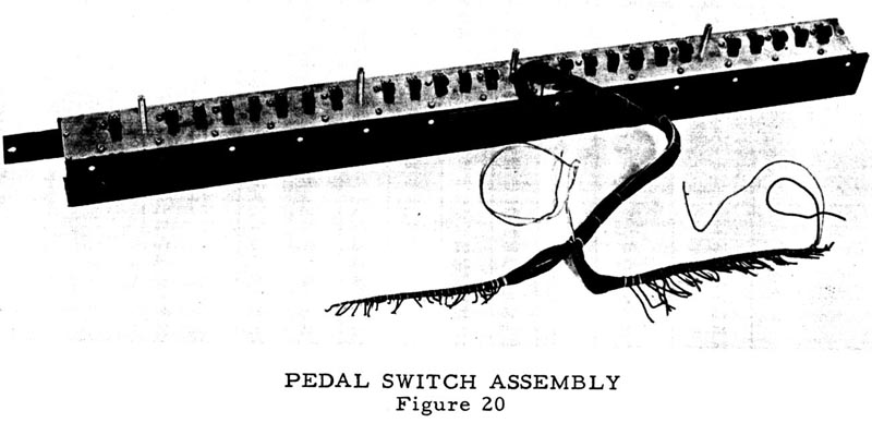
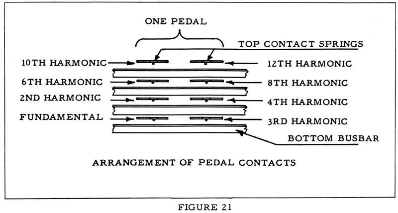
The pedal switch (shown in Figure 20) is similar in internal construction to the manuals except that only four busbars are included instead of nine (Figure 21). Each of the 25 pedals actuates a double set of contact springs, making eight contacts available for each note. Each note consists of a fundamental and a number of harmonics, no sub-harmonics being used. The pedal contact springs are connected to terminals by resistance wires similar to those used in the manual assembly, and a cable connects these terminals to the proper terminals on the generator terminal strip.
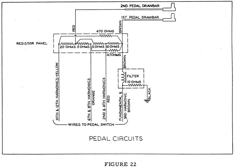
Four colored wires carry the pedal tones from the busbars to the pedal drawbars. The wires are connected first to a resistor panel on the back of the manual assembly. A small choke coil and resistor mounted on the manual assembly are wired to the lower drawbar (see Figure 22) and serve to filter out any higher harmonics or transients which might be present in the lower pedal frequencies.
Figure 23 is a wiring chart for the pedals,showing the frequency numbers appearing on each pedal contact.
| Pedal #. | Note | Fund | 2nd Harm/3rd Harm | 2nd Harm | 4th Harm | 6th Harm | 8th Harm | 10th Harm | 12th Harm |
| 1 | C | 1 | 13 | 13 | 25 | 32 | 37 | 41 | 44 |
| 2 | C# | 2 | 14 | 14 | 26 | 33 | 38 | 42 | 45 |
| 3 | D | 3 | 15 | 15 | 27 | 34 | 39 | 43 | 46 |
| 4 | D# | 4 | 16 | 16 | 28 | 35 | 40 | 44 | 47 |
| 5 | E | 5 | 17 | 17 | 29 | 36 | 41 | 45 | 48 |
| 6 | F | 6 | 18 | 18 | 30 | 37 | 42 | 46 | 49 |
| 7 | F# | 7 | 19 | 19 | 31 | 38 | 43 | 47 | 50 |
| 8 | G | 8 | NC | 20 | 32 | 39 | 44 | 48 | 51 |
| 9 | G# | 9 | NC | 21 | 33 | 40 | 45 | 49 | 52 |
| 10 | A | 10 | NC | 22 | 34 | 41 | 46 | 50 | 53 |
| 11 | A# | 11 | NC | 23 | 35 | 42 | 47 | 51 | 54 |
| 12 | B | 12 | NC | 24 | 36 | 43 | 48 | 52 | 55 |
| 13 | C | 13 | 32 | 25 | 37 | 44 | 49 | 53 | 56 |
| 14 | C# | 14 | 33 | 26 | 38 | 45 | 50 | 54 | 57 |
| 15 | D | 15 | 34 | 27 | 39 | 46 | 51 | 55 | 58 |
| 16 | D# | 16 | 35 | 28 | 40 | 47 | 52 | 56 | 59 |
| 17 | E | 17 | 36 | 29 | 41 | 48 | 53 | 57 | 60 |
| 18 | F | 18 | 37 | 30 | 42 | 49 | 54 | 58 | 61 |
| 19 | F# | 19 | 38 | 31 | 43 | 50 | 55 | 59 | 62 |
| 20 | G | 20 | 39 | 32 | 44 | 51 | 56 | 60 | 63 |
| 21 | G# | 21 | 40 | 33 | 45 | 52 | 57 | 61 | 64 |
| 22 | A | 22 | 41 | 34 | 46 | 53 | 58 | 62 | 65 |
| 23 | A# | 23 | 42 | 35 | 47 | 54 | 59 | 63 | 66 |
| 24 | B | 24 | 43 | 36 | 48 | 55 | 60 | 64 | 67 |
| 25 | C | 25 | 44 | 37 | 49 | 56 | 61 | 65 | 68 |
| Frequency Number | |||||||||
Frequencies used in pedal switch (Figure 23)
Pedal Switch Busbar Shifters
The pedal switch is equipped with busbar shifters similar to those on the manuals. The pedal busbar shifter is a Slotted stud on the near surface of the pedal switch, near the left end as you look in at the back. It should be adjusted as described under "Manual Busbar Shifters" on a previous page.
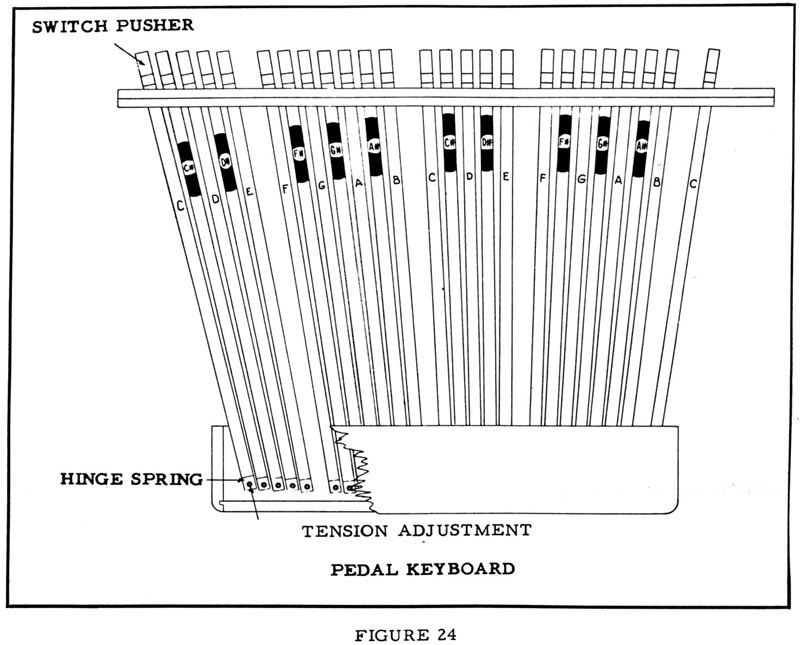
Pedal Keyboard
Pedal keys are set at the factory for average tension, but are adjustable to fit the requirements of the individual organist. Adjustment is accomplished by removal of the top cover at the back of the pedal keyboard and setting the tension as desired.
THE HAMMOND VIBRATO
PRINCIPLE OF OPERATION
The vibrato effect is created by a periodic raising and lowering of pitch, and thus is fundamentally different from a tremolo, or loudness variation. It is comparable to the effect produced when a violinist moves his finger back and forth on a string while playing, varying the frequency while maintaining constant volume.
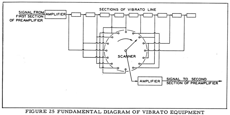
The Hammond Organ vibrato equipment (see simplified block diagram, Fig.25) varies the frequency of all tones by continuously shifting their phase. It includes a phase shift network or electrical time delay line, composed of a number of low pass filter sections, and a capacity type pickup or scanner, which is motor driven so that it scans back and forth along the line.
Electrical waves fed into the line are shifted in phase by each line section (the amount per section being proportional to frequency), so that at any tap on the line the phase is retarded relative to the previous tap.
The scanning pick-up traveling along the line will thus encounter waves increasingly retarded in phase at each successive tap, and the signal it picks up will continuously change in phase. The rate at which this phase shift occurs will depend on how many line sections are scanned each second.
Since a cycle is equivalent to 360 electrical degrees, a frequency shift of one cycle occurs for each 360 electical degrees scanned per second. For example if the scanner passes over the line at such a rate that 3600 electrical degrees are scanned each second, there will be a frequency change of 10 cycles.
For the widest vibrato, the whole line is scanned from beginning to end in about 1/14 second, and this rate of change of phase causes about 1-1/2% decrease in frequency. Note that the frequency remains constantly 1-1/2% low as long as the moving pick-up retards the phase at a constant rate.
Since the pick-up sweeps from start to end of the line and then back, it increases the frequency by an equal percentage on its return trip, the average output frequency remaining equal to the input frequency. The exact amount of frequency shift depends not only on the amount of phase shift in the line but also on the scanning rate. This rate, however, is constant because the scanner is driven by the synchronous running motor of the organ.
The degree of vibrato (or amount of frequency shift) may be varied by a switch (not shown in Fig. 25) which causes the whole line to be scanned for #3 (wide) vibrato, about half of it, for #2, and about one third for #1.
A vibrato chorus effect, similar to the effect of two or three slightly out-of-tune frequencies mixed together, is obtained when the vibrato output signal is mixed with a portion of signal without vibrato. For vibrato chorus, part of the incoming signal appears across the vibrato line and the rest across a resistor in series with the line. As the vibrato effect is applied to the part of the signal appearing across the line, but not to the part appearing across the resistor, the combination produces a chorus effect. For normal vibrato, this resistor is short-circuited.
CONSTRUCTION OF COMPONENTS
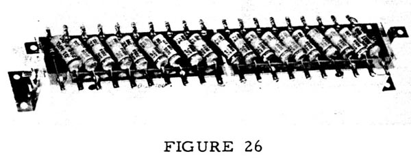
Figure 26 shows the vibrato line box.
Each of the inductance coils, with a capacitor, forms one filter section.
Figure 27 shows the construction of the vibrato switch.
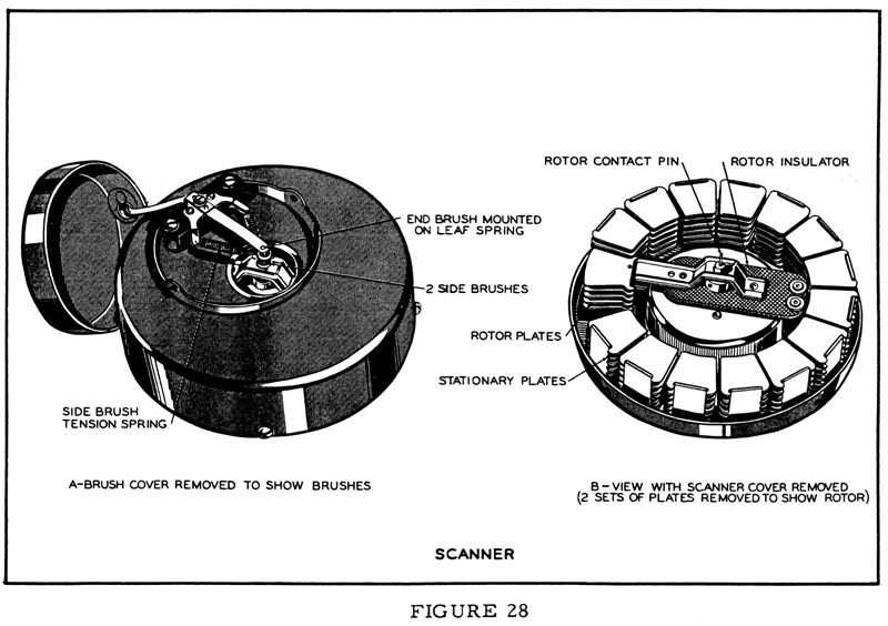
The scanner (Fig. 28) is mounted on the main generator synchronous motor and driven at 412 revolutions per minute. It is a multi-pole variable condenser with 16 sets of stationary plates and a rotor whose plates mesh with the stationary ones. In figure 28B two sets of plates have been removed to show the rotor.
Signals coming from the line through the vibrato switch appear on the stationary plates and are picked up, one at a time, by the rotor. Connection to the rotor is made by carbon brushes as shown in Figure 28A. Two brushes touch the sides of the contact pin and a third presses on.the end, in order to eliminate the possiblity of contact failure.
The complete schematic shows the vibrato circuit.

HAMMOND TOUCH-RESPONSE PERCUSSION CONTROL
1. THEORY OF OPERATION
The percussion tones are produced by borrowing the 2nd or 3rd harmonic signal from the corresponding drawbar (of the upper manual "B " adjust key drawbar group), amplifying it, returning part of it to the same drawbar, and conducting the balance through push-pull control tubes, which when keyed cause the signal to fade away at a pre-determined rate.
2. GENERAL CIRCUIT OPERATION (All Reference Is To Schematic diagram - End of Book.)
With percussion tablet "on" upper manual "B" adjust key and an upper manual playing key pressed, the 2nd or 3rd harmonic signal appearing on an upper manual busbar is conducted through "B" adjust key drawbar wire to input of percussion amplifier (terminal H) and amplified by T4 and V5. Besides providing push-pull signal for the control tube V7, the percussion input transformer T5 has a third winding which feeds the signal back to the 2nd or 3rd harmonic drawbar through equivalent key circuit resistor R50 and terminal J. Thus the signal that was borrowed from the 2nd or 3rd harmonic drawbar for the percussion amplifier is replaced.
When a key is depressed the signal first sounds loudly through the control tube, transformer T6, a high pass filter, and terminal D to the grid of V4. Immediately condenser C31 in the control tube grid circuit begins to discharge, causing the signal to fade away. This circuit works as follows: Terminal K (approximately +25 volts) is connected to the 8th harmonic "B " adjust key drawbar wire which is connected to the manual busbar. Pressing any upper manual key grounds terminal K through the tone generator filters. This virtually grounds the plate of Vb (connected as a diode), stops conduction, and isolates cathode and control tube grid circuits. The grid then drifts from approximately +25 volts to about +15 volts, at a rate determined by the time required for C31 to discharge through R57 and R58. At the completion of this sequence, the percussion signal is blocked. No further percussion effects occur until all keys of the upper manual are released and control grids can again rise to +25 volts. The rate of this rise is fixed by the time required to charge C31 to +25 volts through R55 and R56.
3. FOUR PERCUSSION CONTROL TABLETS, CUTOFF CONTROL, AND THEIR FUNCTIONS.
The Percussion On-Off Tablet when turned "on" does five things to the signals of the upper manual "B" adjust key drawbars.
(a) It disconnects the 2nd harmonic drawbar from its signal wire.
(b) It disconnects the 3rd harmonic drawbar from its signal wire.
(c) It connects the 2nd or 3rd harmonic drawbar signal wire (depending on position of Percussion Harmonic Selector Tablet) to input of percussion amplifier.
(d) It disconnects the 8th harmonic drawbar from its signal wire. This wire (which will be connected through generator filters to ground when any key is pressed) is connected to terminal K. The 8th harmonic signal is not available on the upper manual as long as the percussion tablet is "on".
(e) It inserts resistor R1 in series with upper manual matching transformer (T2) secondary to reduce upper manual organ signal so that lower manual will musically balance with the combined upper manual organ and percussion signals.
The Preset Percussion Switch is not part of the control tablet assembly or percussion on-off tablet, but functions as an interlock with them. It is located under the upper manual "B" adjust key. This switch insures that the full upper manual signal is restored by shorting out series resistor R1 introduced by the percussion "on" tablet when any other upper manual preset or adjust key is pressed.
The Volume Tablet in "soft" position shunts resistor R46 across the percussion output transformer, reducing the percussion signal, and also shorts out upper manual matching transformer compensating resistor R1 thus restoring the upper manual signal strength to provide proper balance between the manuals.
The Decay Tablet in "fast" position shunts resistor R57 across the slow decay resistor R58 reducing time for decay capacitor C31 to discharge and for V7 controls grids to reach cut-off. Also, to preserve the same effective loudness in "fast decay" position as in "slow decay, " the control tube bias is reduced by disconnecting R59 and allowing the control tube grids to become more positive, which increases output signal about 50%.
The Harmonic Selector Tablet does three things to the signals of the upper manual "B" adjust key drawbar group:
In "Second" Position:
(a) It connects the 2nd harmonic signal wire to percussion amplifier input.
(b) It connects the 3rd harmonic signal wire to the 3rd harmonic drawbar.
(c) It connects the signal from terminal J to 2nd harmonic drawbar.
In "Third " Position:
(a) It connects the 3rd harmonic signal wire to the percussion amplifier input.
(b) It connects the 2nd harmonic signal to the 2nd harmonic drawbar.
(c) It connects the signal from terminal J to the 3rd harmonic drawbar.
The Percussion Cut-off Control, which is located on the pre-amplifier, should be readjusted as follows whenever control tube V7 is replaced: Set expression pedal wide open, both volume tablets "normal" percussion "on", percussion decay "fast", and harmonic selector in either position. Depress any key in upper half of upper manual and then adjust cut-off control exactly to the point where signal becomes inaudible.
EARPHONES
Earphones can be added to the console for practice purposes so as not to distrub others. Earphones at best cannot replace the tonal quality achieved from the instruments' own speakers but do make the organ "more available"
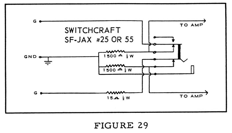
One method of attaching earphones is shown in the sketch below, using a reluctance type headset of good quality. Inserting the phone plugs silences the speakers in the console. Wiring is between the preamplifier terminals marked "G" and the main amplifier input.
PHONO INPUT
A microphone or record player pickup may be used through the organ if desired. The preamplifier is equipped with a standard phonograph input jack. The input impedance is approximately 1 megohm and the circuit requires a maximum input signal of about 1/2 volt. A volume control will have to be installed between the microphone or record player input and the organ inasmuch as the swell control of the organ does not affect this input.
SCHEMATICS
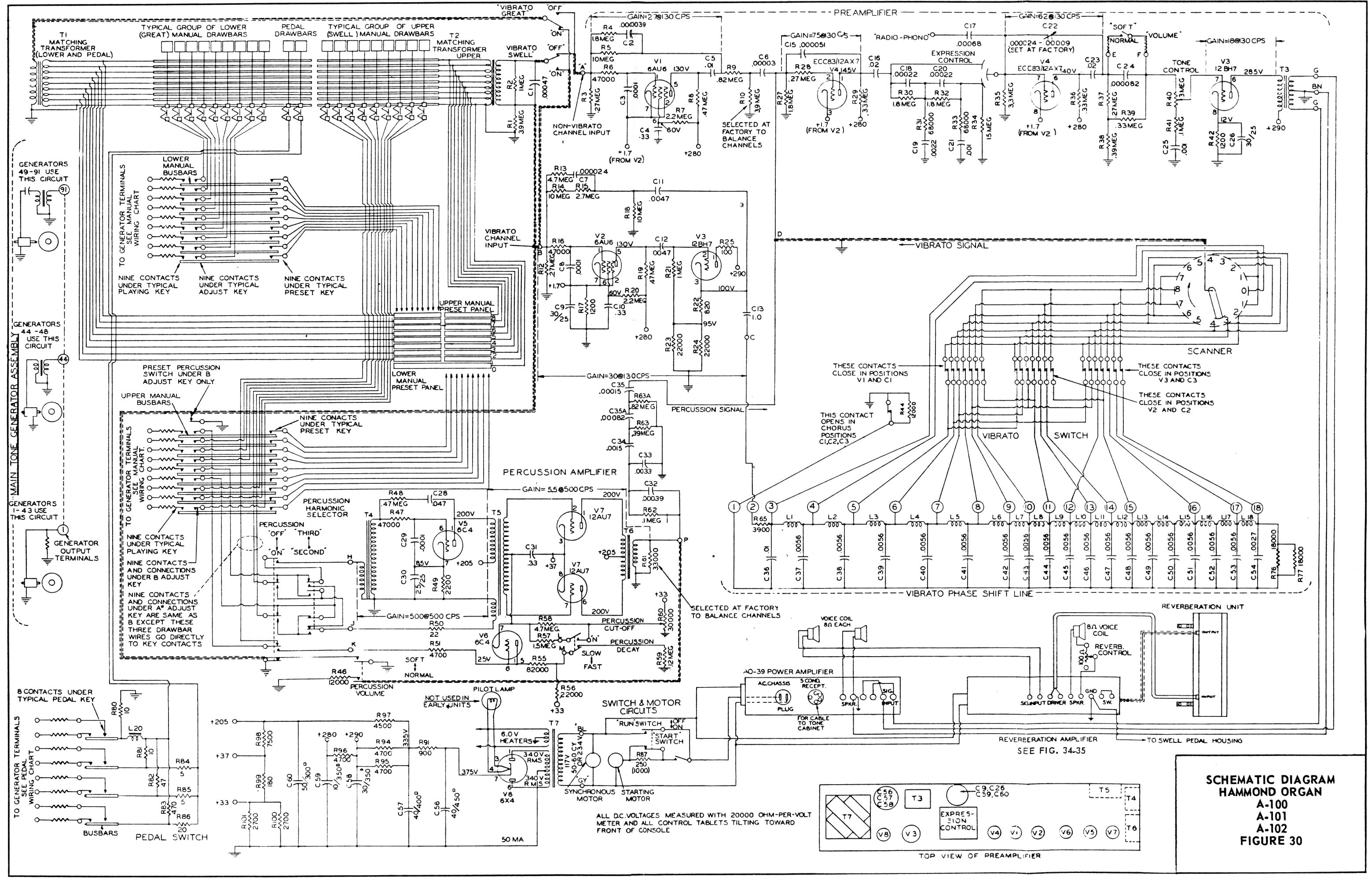
Schematic #1 - Figure 30 - Hammond Organ models A-100, A-101, A-102 schematic.
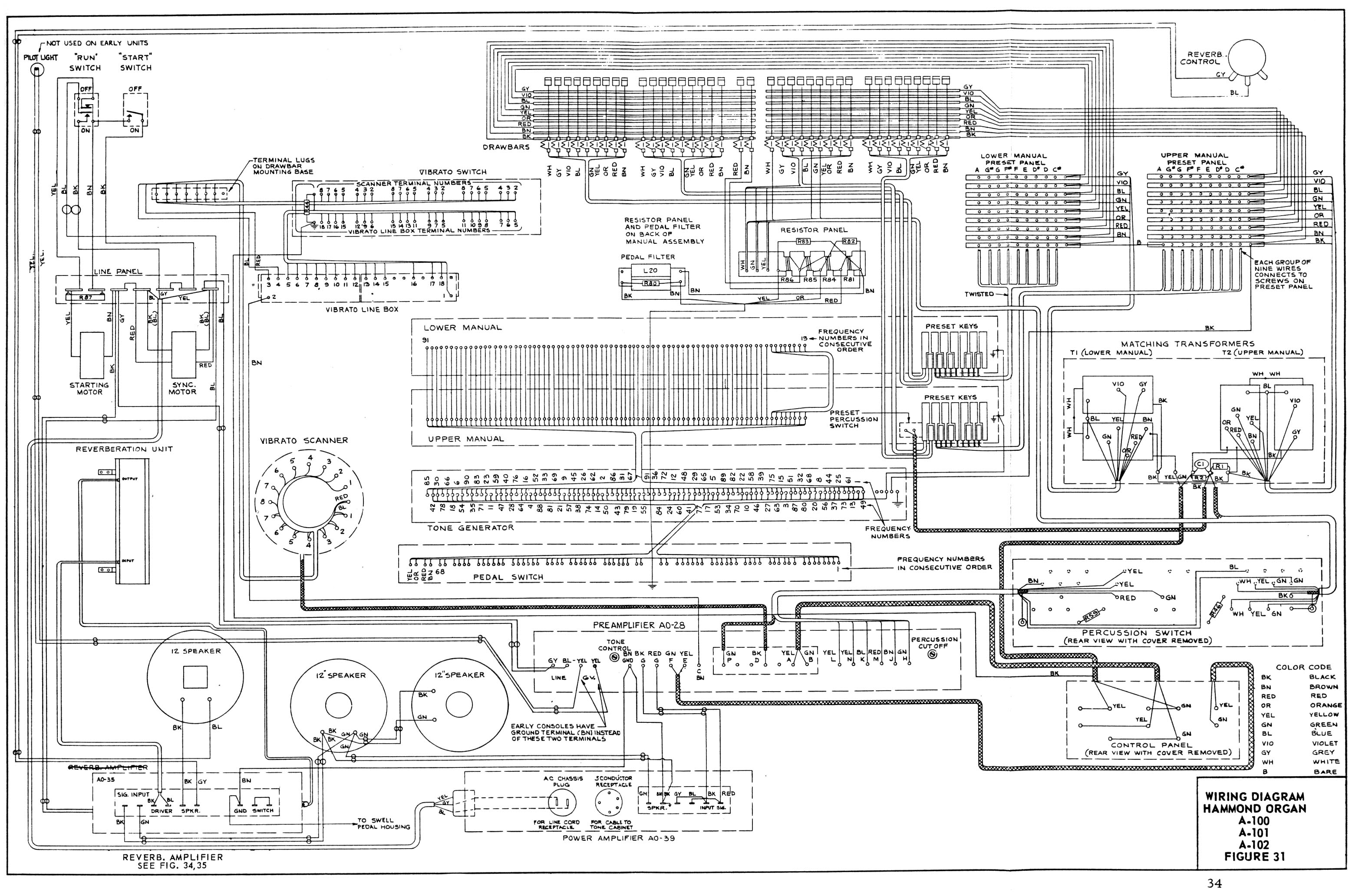
Schematic #2 - Figure 31 - Hammond Organ models A-100, A-101, A-102 wiring diagram.
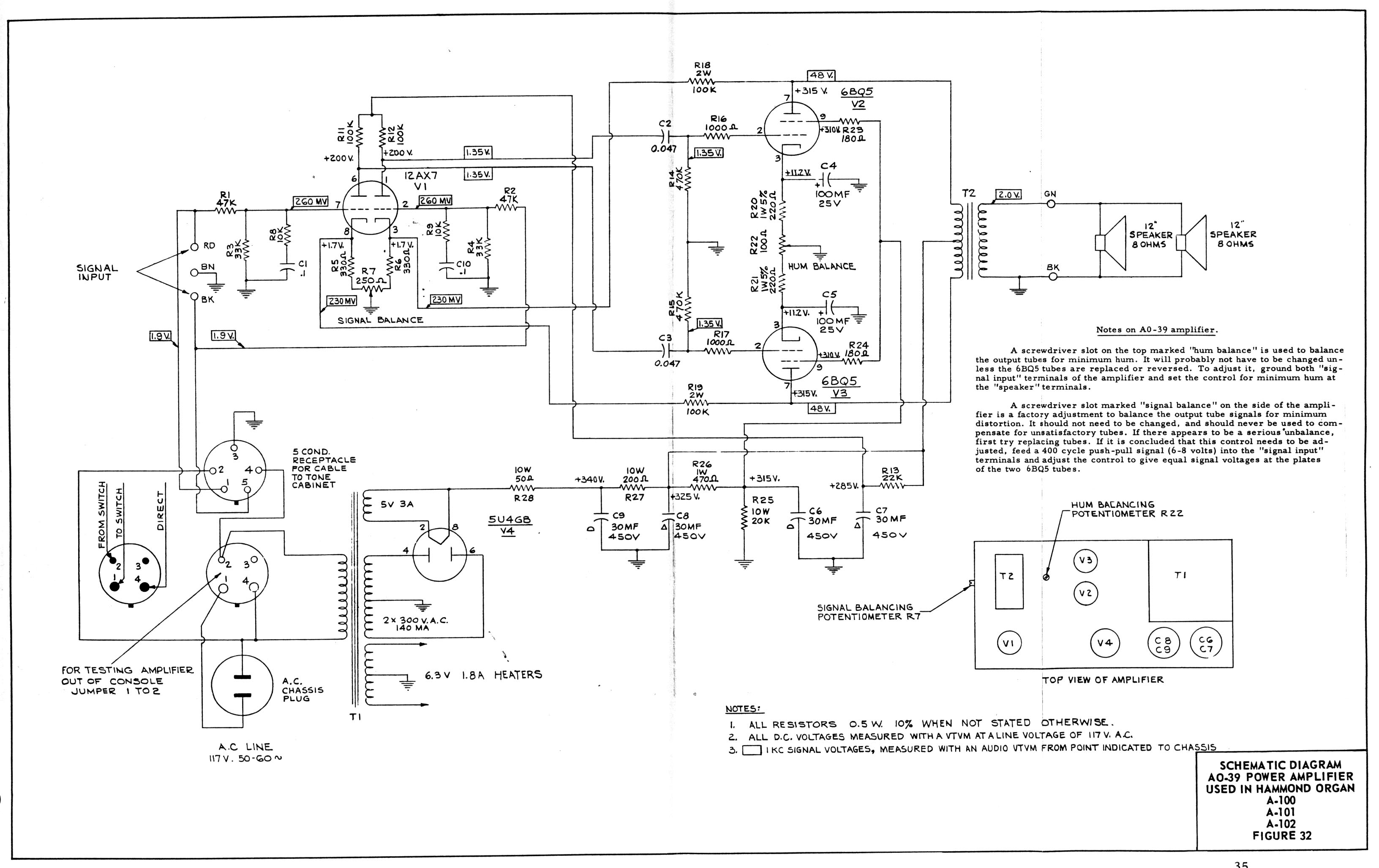
Schematic #3 - Figure 32 - AO-39 Power Amplifier schematic.
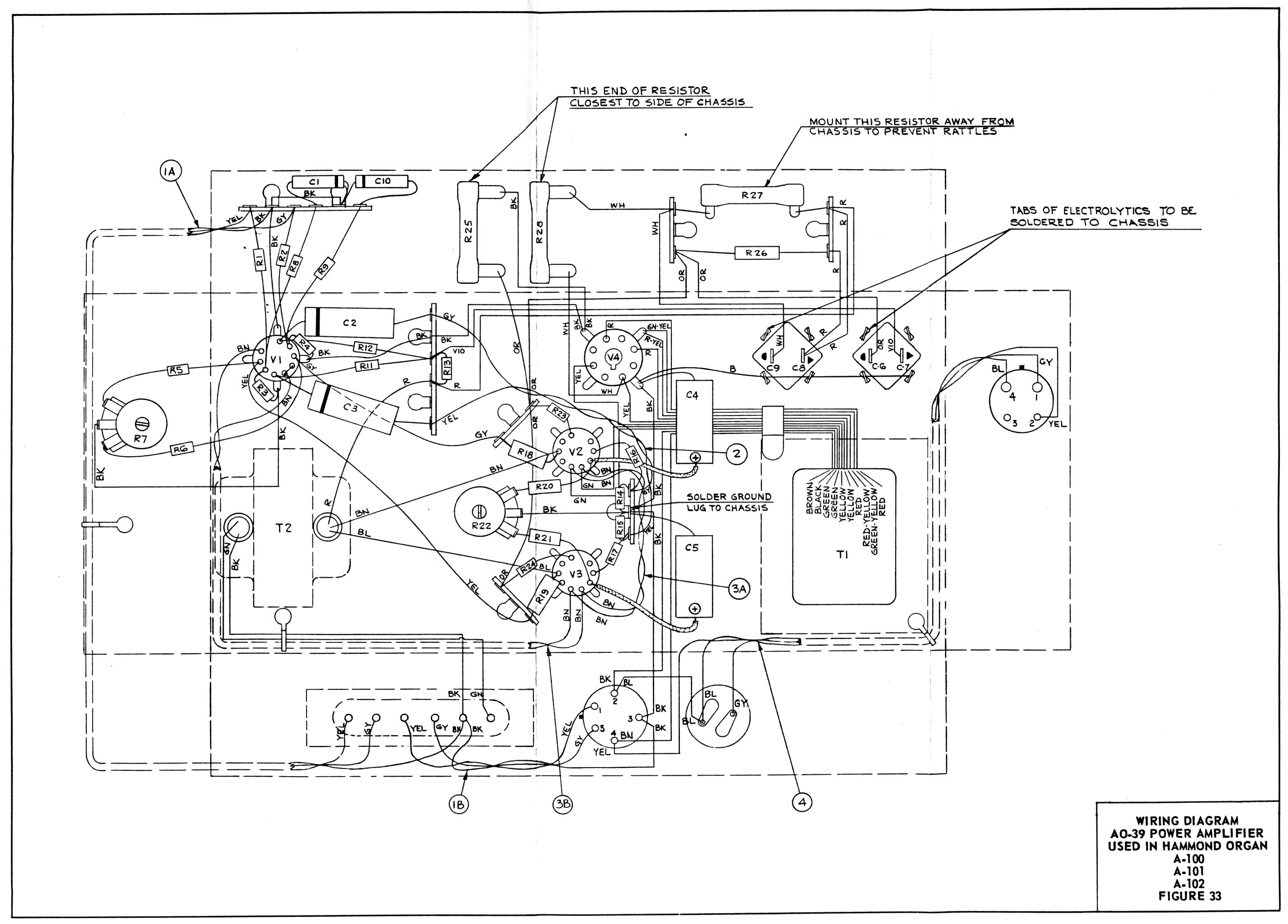
Schematic #4 - Figure 33 - AO-39 Power Amplifier wiring diagram.
