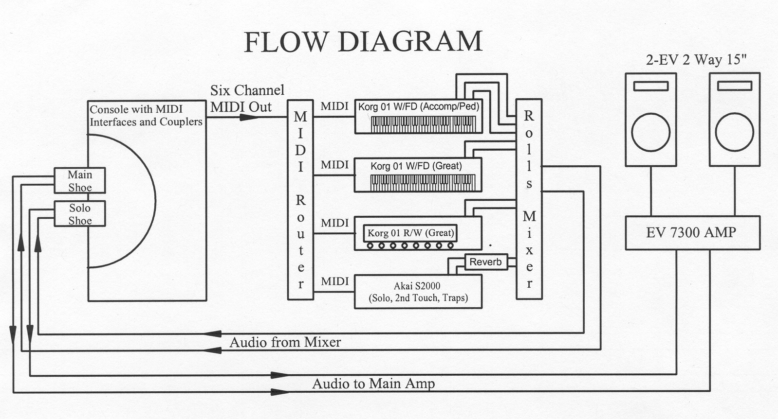
CIRCUITRY
Basically my console uses 3VDC key switching to drive a bank of optoisolators attached to Casio synthesizer ‘mother’ boards where the synthesizer’s keys used to be. The keying voltage logic enables controls to easily function like those on a Theater Pipe Organ, and to be located in the same places as on a Theater Pipe Organ. The optoisolater system triggers the Casio mother boards to output MIDI signals to control modern day synthesizers in a way that they 'understand'. Thanks to this hybrid control combination, virtually every function in a Theater Pipe Organ can be duplicated by synthesizers using MIDI interfaces. In addition, the control logic is easily modified and expanded in a way any Pipe Organ tech can understand.
I bought the most basic Casio synths I could find that had a MIDI output. The sound the units made was not important since they are only being used as MIDI interfaces. These units did NOT have touch sensitivity, so each key had only two contacts, just like pipe organ circuitry. This made control of the units with a keying voltage much simpler. Velocity sensitivity was not required when duplicating the function of a Theater Pipe Organ, the keys were either full on or full off. The units were capable of sending note on/off messages, MIDI program change messages, could transmit MIDI data on any of the 16 channels, and even had an input for a 'hold' pedal if I wanted sustuenedo.
The Casio Keyboard used what is called matrix keying. There were 8 inputs for data, and 8 inputs 'scanning'. That way only 16 wires need be run from keyboard to mother board instead of one for each of the 61 keys plus a common. The keying system could in theory handle 64 keys, but there are only 61 keys on a five octave keyboard.
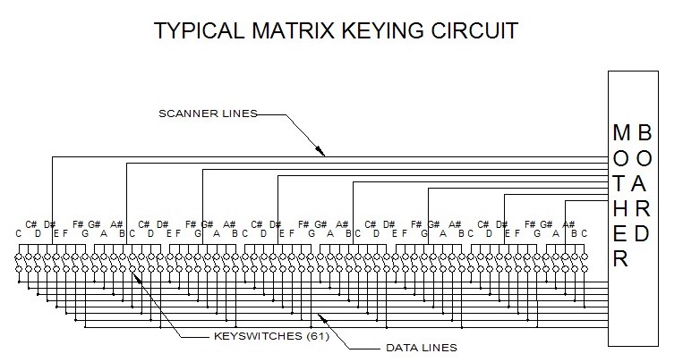
Each of the data leads is wired to every 8th key. The ‘scan’ inputs act as commons for the key contacts. Each one spans 8 notes. Which data lead is connected to which 'scan' input determines the note(s) played and the MIDI signal output.
It would be a relatively simple matter merely to duplicate this contact system using a pipe organ manual. After the existing wiring is taken out, all you would have to do is split the keyswitch common every 8 notes, and commonly wire every 8th key. If you are building a MIDI based organ, and have no need for couplers or trap lines, this is a simple way to go. If you want the increased functionality of trap lines, couplers, effects on toe studs and Second Touch, a more complex system is required
Because I wanted more advanced functionality, I built the optoisolator circuitry shown below. The keyswitches are wired like the usual pipe or electronic organ manuals, one wire per key. The common voltage is 3VDC, and each optoisolator feeds an individual scan-line/data-line connection. Feeding into each optoisolator is a 1K current limiting resistor. Looking back at the circuit, I could have used about 2.2K resistors and a 5V keying voltage. 5V was tried originally, but when a good number of circuits were played at once, especially with the coupler stack in use, some feedback problems came up that were not predicted. It takes a very small current to trigger the optoisolators, and leakage through some circuitry may have caused this. With 3VDC, and 1K current limiting resistors, I have had no problems in 5 years of operation except with loose solder joints.
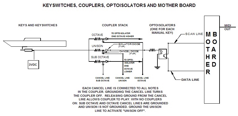
The reason the DC keying was employed is the coupler stack. Use of diode/resistor logic enables me to have completely solid state coupler switches without the moving contacts used on most pipe organ ‘gang switches’. If you were reworking an older Allen console, many of these had gang switches for couplers wired in, and this logic could simply be used to key the optoisolators.
The logic for a coupler stack is shown above. For each note in each coupler, two diodes and a resistor are required. When the coupler is not in use, the ‘cancel line’ for each note in the coupler is grounded, and keying current flows from keyswitch through the resistor, through the cancel diode to ground. It cannot reach the optoisolator. Thanks to the isolating diode, current cannot flow backward from the optoisolator to the ‘cancel diodes’ or to any of the other key voltage leads that could potentially play this note, so no feedback or undesired notes are possible when everything is operating properly. Couplers can couple a given manual to itself at octaves, higher and lower. They can also couple one manual to another at Unison pitch, or octaves above or below. Harmonic couplers could couple manuals together at 5ths, thirds, 7ths, or whatever else can be imagined. Any manual can also be coupled to the Pedal. I utilize manual couplers to couple the Great to itself at an octave above and/or below. The same for the Solo manual. The Solo may also be coupled to the Great at three pitches, Sub octave, Unison and Octave. The Accompaniment couples to itself at the octave, and couples to the Pedal at Unison. In addition, Second Touch couplers join the Great and Solo to the Accompaniment, and the Solo to the Great at Sub Octave and Unison. If you were installing Second Touch, a simplified way to do it would be to make the Second Touch a coupler division only. It saves on an extra MIDI converter for that division, since all the second touch would do is play OTHER existing divisions that already have MIDI converters. George Wright’s Hollywood Philharmonic Organ had Solo to Great couplers as the only stops on the Great Second Touch division.
In addition to keying notes, program changes must be sent to each synth or division. Luckily the Casio units do this whenever patches are changed on their front panel. Not only do these Casio mother boards act as a MIDI interface for notes played, they also act as an interface for MIDI program changes. On the Casios, each program change requires pressing two buttons, a '10s' digit and a '1s' digit. They are like 'Bank Selector' and 'Patch' buttons. Two button operation is not desired on a Theater Organ where pressing a single button or piston is expected to change the sound. To make the Casio 'MIDI Interface' behave more like a Theater Organ combination action, I built a system that converts the pressing of a single combination piston to the pressing of bank and patch number buttons on the Casio motherboards. Which bank or '10s' button is selected depends on which bank piston is selected on the console. The Casio's '1s' button is the same as the piston pressed. The same optoisolator circuitry is used to activate program changes because the Casio mother boards use the same matrix type switching to make program changes as they do for playing keys. The same holds true for when the initial MIDI channel is selected for each motherboard when the organ is turned on. If building such a system is beyond your skill level, there are both keying and patch selection circuits available commercially. These easily install on either existing electronic organs or kits are available to retrofit pipe organ consoles.
In contrast to the 'pistons only' way that the manuals are registered, The Accompaniment and Great Second Touch divisions work with a true stop tablet action. This is possible is because each of these divisions has a very small number of stops. Remember that the way a sound is changed is by changing a synthesizer ‘patch’. This ‘patch’ either on the Korgs or the Akai, is a ‘combination’, consisting of a number of ‘programs’. Each 'program' prepresents a single stop. If, on a given division, there were only 4 stops, then there are only 16 possible stop combinations on that division. Within a synthesizer, 16 combinations or patches would cover every setting you could make with these 4 tablets. I built a logic circuit that scans the stoptablet switches and outputs a MIDI program change based on what tablets are down. The circuit only sends a program change message if a change in the stoptablet setting is noted. Second Touch divisions are usually small, so 4 stops are enough. I added a 5th stop on the Accompaniment by having the Posthorn come on every time the Tuba and Harp (a very illogical combination musically) are pushed down together. Fortunately this system does NOT have to extend to either the couplers or Second Touch traps. You can have as many of those as you like without complicated switching logic. As you may have guessed, the two Second Touch divisions each have their own Casio mother board acting as a MIDI converter, just as the regular manuals do. The Second Touches operate on 3VDC keying voltage, and they can send out program change messages.
In my setup, the Second Touch key and program change information is processed by the Akai sampler. Each Second Touch division, like every manual and Pedal division, is on a separate MIDI channel. The Akai has the ability to process 16 different ‘parts’ at once, each on a different MIDI channel. No one part has any idea of that the others are doing, and it’s a good thing. Within a given part, for instance, operated on MIDI channel 5, notes can play and program changes be made, all on channel 5, and no other part in the synthesizer is affected at all. Remember that while playing this Second Touch stuff, this same sampler has the Solo manual in its entirety to deal with. The Akai also handles untuned percussions and effects. One of the Akai’s ‘Parts’ is set up to receive MIDI channel 1, the same channel as the pedals. It only responds to notes ABOVE the usual 32 pedal notes. The bottom ones are handled by the same Korg 01 that plays the Accompaniment. The MIDI converter that handles the Pedal division is from a less expensive Casio, and transmits 49 notes. Beyond the Pedal division, this leaves 17 notes ‘spare’. Onto these note locations in the sampler have been placed untuned percussion samples: drums, cymbals, crash cymbals tambourine etc. The same looping technique that was described for reiterating tuned percussions is used for the reiterating Snare Roll, Tambourine and Castinets. All of these percussions were sampled from a Roland DR5 drum machine. There is also a Cymbal Roll or Persian Cymbal. This was sampled from a ride cymbal with a long decay being struck repeatedly by sequencing multiple strokes at roll speed on the Roland DR5. It is not a looped sample, but plenty long so it probably would never ‘run out of gas’ in normal use. Of course each of these percussion samples is triggered by the same type of circuit that operates the keys. The 3VDC trigger voltage can be applied in any way it can in a Theater Pipe organ: trap lines, toe studs, push buttons, whatever. If you do this on your instrument bear in mind that you are NOT limited to purely musical effects. This is where your sound effects like Train Whistle, Surf, Car Horn, and the like could come from, in fact, it’s the best source for these. I even experimented with a sample of actual pipe organ blower and wind noises.
Although the method of control of various MIDI functions is not the most sophisticated available, it is the simplest way to duplicate the controls found on a Theater Pipe Organ. Rather than try to bend and shape MIDI to conform to the control systems found on a Theater Pipe Organ, I merely control MIDI WITH these same systems. The control logic using DC keying voltage is done exactly the way it is done on a Theatre Pipe Organ. The trap lines, effects controls and other gadgets are all available to the organist, operating in the same way and located in the same place as any Theater Pipe Organ. The circuitry is just as easily modified as in any Theater Pipe Organ, too, so hobbiests can add, subtract and tinker to their hearts content.